HOW TO USE DEBUGGER/SIMULATOR
The following figure is a screenshot from the main page. There are nine different panels on the screen.
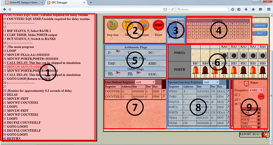 1) PROGRAM PANEL: Here, you see the codes compiled by Online PIC Compiler. This panel scroll above and below, automatically,
depending on the current line to be processed, while simulating the instructions in the program. The current line to be processed is coloured in red.
1) PROGRAM PANEL: Here, you see the codes compiled by Online PIC Compiler. This panel scroll above and below, automatically,
depending on the current line to be processed, while simulating the instructions in the program. The current line to be processed is coloured in red.2) SIMULATION PANEL: There are four buttons controlling the flow of simulation, on this panel.
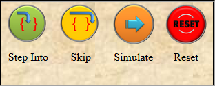
- Step Into: Push Step Into button to simulate your program just one instruction.
- Skip: Push Skip button, if you want to skip the line current line without processing.
- Simulate: Push this button to simulate 100 steps (instructions). During the simulation, you can stop it, by pushing the same button again. After 100 steps, the program stops, automatically. Pressing Simulate button again, leads to continue simulation 100 steps more. The simulation speed can be adjusted from the "range" appears below the buttons when simulation starts.
- Reset: This button resets the program.
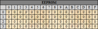
4) EEPROM PANEL: 16F84A has a 64 byte EEPROM space with addresses 0 to 63. EEPROM panel illustrates the content of EEPROM in each address space.
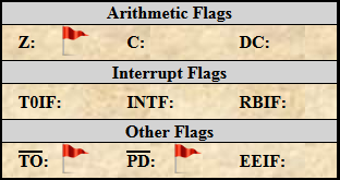
5) FLAG PANEL: On this panel, flag bits of 16F84A are illustrated. If a flag is ON, a flag image appears next to the name; otherwise it dissappaers.
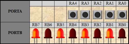
6) PORT PANEL: Port panel is composed of LEDs and interactive buttons. If a port is set to be input, a toggle button appears; in the output case, a LED appears under the name of that port. If the image under the port name is a button, the user can change its logic level by clicking on it.
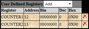
7) REGISTER PANEL-1: On Register Panel-1, the user-defined registers appear. The declared address, binary, decimal and hexadecimal representations of the content can be seen for each register defined. The user can remove from or add registers to this list.
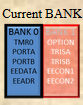
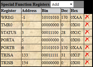
8) REGISTER PANEL-2: On Register Panel-2, the special function registers such as STATUS, OPTION, PORTA and etc. appear. The declared address, binary, decimal and hexadecimal representations of the content can be seen for each register. The user can remove from or add registers to this list.
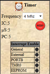
9) TIMER/INTERRUPT PANEL: The user can keep the track of total time passed in terms of instruction cycles and microseconds on this panel after selecting the frequency of the crystal used in hardware. Moreover these timers can be reset by pushing the RESET button on the panel.
Moreover, the program counter, PC, is shown under the timer.
Furthermore, the current states of the interrupt enabled bits can be followed from this panel.