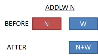
ADDLW affects the flags Z, DC and C. Zero Flag (Z) is set if the result of the summation is equal to zero (or 256).
In the example below because the result is 78 (different from 0) Z=0 at the end of ADDLW instruction.
Digit Carry Flag (DC) is set if a carry from the lower nibble
(the least significant 4 bits) to the upper nibble(the most significant 4 bits) occurs. In the example below, the lower nibbles
of W and N are F(=15 in decimal) and 1(=1 in decimal), respectively. The summation of the lower nibbles is 10(=16 in decimal) which means
there is a carry from the lower nibble to the upper (F+1=0 with a carry). Therefore at the end of ADDLW operation DC=1.
Carry Flag (C) is set if the result of the summation is greater then 255,
or in other words, there exists and overflow. In the example below because the result is 300 and W is an 8- bit register 300-255=45 is hold in W and C=1.
Note: All three flags are affected and changed after a single ADDLW operation at the same time.
In the example below, the result is nonzero, then Z=0. There is an overflow, so C=1. In lower nibbles there is a carry, as well, so DC=1.
ADDWF adds the content of the File Register FR to W, and writes the result to the destination D.
If the destination D=1 or F the result is written to FR; if it is 0 or W, the result is written to W register.
Example: Let's say W=D'15' and the register COUNTER is equal to D'63',initially. Then ADDWF COUNTER, 0
makes W=15+63=78
Note: ADDWF FR, D adds the content of FR, NOT the address.
In the following example address of COUNTER is 0X20 but the content is set to 0X05 with MOVLW and MOVWF instructions. The address 0x20 does not affect the result.
Note: The destination D (=0, W, 1 or F) is not effective on the flags.
Zero Flag (Z) is set if the result of the summation is equal to zero (or 256).
In the example below because the result is 78 (different from 0) Z=0 at the end of ADDWF instruction.
Example:
Let's say W=15 and COUNTER=63, then ADDWF COUNTER, F
makes COUNTER=78. W remains the same. If the destination was W (or 0), W becomes 78 and COUNTER remains the same.
However, in the example below the result is zero (256=0 for an 8-bit storage area), and Z=1 at the end of ADDWF instruction.
Example:
Let's say W=193 and COUNTER=63, then, ADDWF COUNTER,1 ;COUNTER=193+63=256=0
Digit Carry Flag (DC) is set if a carry from the lower nibble
(the least significant 4 bits) to the upper nibble(the most significant 4 bits) occurs. In the example below, the lower nibbles
of W and COUNTER are F(=15 in decimal) and 1(=1 in decimal), respectively. The summation of the lower nibbles is 10(=16 in decimal) which means
there is a carry from the lower nibble to the upper (F+1=0 with a carry). Therefore at the end of ADDWF operation DC=1.
Example:
Let's say W=0X01 and COUNTER=0X0F, then, ADDWF COUNTER, 0 ;W=0X01+0X0F=0X10
However, in the example below the summation of lower nibbles is F without a carry, then DC=0.
Example:
Let's say W=0X01 and COUNTER=0X0E, then, ADDWF COUNTER, W ;W=0X01+0X0E=0X0F
Carry Flag (C) is set if the result of the summation is greater the
n 255,
or in other words, there exists and overflow. In the example below because the result is 300 and W is an 8- bit register 300-255=45 is hold in W and C=1.
Example:
Let's say W=D'50' and COUNTER=D'250', then, ADDWF COUNTER, 0 ;W=50+250=300=45
However, in the example below the result is less than 255 and C becomes 0.
Example:
Let's say W=D'190' and COUNTER=D'63', then, ADDWF COUNTER, W ;W=190+63=253
Note: All three flags are affected and changed after a single ADDWF operation at the same time.
In the example below, the result is nonzero, then Z=0. There is an overflow, so C=1. In lower nibbles there is a carry, as well, so DC=1.
Example:
Let's say W=0X0F and COUNTER=0XFF, then, ADDWF COUNTER, 0 ;W=0X0F+0XFF=0X0E
SUBLW N
Subtracts W from N, and writes the result to W.
Example: Let's say W=D'15' ,initially. Then SUBLW D'63'
makes W=63-15=48
Note: If a register name is
written next to SUBLW, then W is subtracted from the address of this register.
SUBLW affects the flags Z, DC and C. Zero Flag (Z) is set if the result of the subtraction is equal to 0.
In the example below because the result is 48 (different from 0), Z=0 at the end of SUBLW instruction.
Digit Carry Flag (DC) is clear, if a borrow from the upper nibble
(the most significant 4 bits) to the lower nibble(the least significant 4 bits) occurs. In the example below, the lower nibbles
of W and N are F(=15 in decimal) and 1(=1 in decimal), respectively. Because the lower nibble of N is smaller than the lower nibble
of W, there exists a borrow from the upper nibble. Therefore, at the end of SUBLW operation DC=0.
Note: All three flags are affected and changed after a single SUBLW
operation at the same time.
In the example below, the result is nonzero, then Z=0. There is a borrow, so C=0. In lower nibbles there is no borrowing, so DC=1.
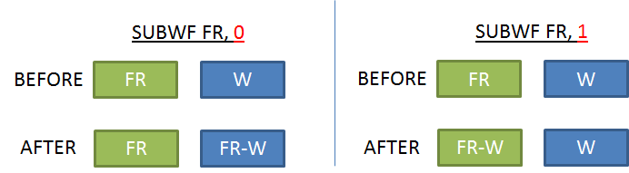
SUBWF subtracts W from the content of the File Register FR, and writes the result to the destination D.
If the destination D=1 or F, the result is written to FR; if it is 0 or W, the result is written to W register.
Example: Let's say W=D'15'
and the register COUNTER is equal to D'63',initially. Then SUBWF COUNTER, 0
makes W=63-15=48
Note: SUBWF FR, D subtracts W from the content of FR, NOT the address.
In the following example address of COUNTER is 0X20 but the content is set to 0X05 with MOVLW and MOVWF instructions.
The address 0x20 does not affect the result.
Note: The destination D (=0, W, 1 or F) is not effective on the flags.
Zero Flag (Z) is set if the result of the subtraction is equal to zero.
In the example below, because the result is 48 (different from 0) Z=0 at the end of SUBWF instruction.
Example:
Let's say W=15 and COUNTER=63, then SUBWF COUNTER, F
makes COUNTER=48. W remains the same. If the destination was W (or 0), W becomes 48 and COUNTER remains the same.
However, in the example below, the result is zero, and Z=1 at the end of SUBWF instruction.
Example:
Let's say W=63 and COUNTER=63, then, SUBWF COUNTER,1 ;COUNTER=63-63=0
Digit Carry Flag (DC) is clear if a borrow from the upper nibble
(the most significant 4 bits) to the lower nibble(the least significant 4 bits) occurs. In the example below, because the lower nibble of W(15) is
greater than the lower nibble of COUNTER(0), DC=0 at the end of the operation.
Example:
Let's say W=0X1F and COUNTER=0X20, then, SUBWF COUNTER, 0 ;W=0x20-0X1F=0X01
However, in the example below the lower nibbles of W is smaller, then DC=1.
Example:
Let's say W=0X01 and COUNTER=0X0E, then, SUBWF COUNTER, W ;W=0X0E-0X01=0X0D
Carry Flag (C) is set if W
Example:
Let's say W=D'50' and COUNTER=D'250', then, SUBWF COUNTER, 0 ;W=250-50=200
However, in the example below, W>COUNTER and C becomes 0.
Example:
Let's say W=D'190' and COUNTER=D'63', then, SUBWF COUNTER, W ;W=63-190=-127=129
Note: All three flags are affected and changed after a single
SUBWF operation at the same time.
In the example below, the result is nonzero, then Z=0. W
Example:
Let's say W=0X0F and COUNTER=0XFF, then, SUBWF COUNTER, 0 ;W=0XFF-0X0F=0XF0
INCF FR, D
INCF increments (adds 1 to) the content of the File Register FR, and writes the result to the destination D.
If the destination D=1 or F the result is written to FR; if it is 0 or W, the result is written to W register.
Example: Let's say
COUNTER is equal to D'63',initially. Then INCF COUNTER, 0
makes W=63+1=64
Note: INCF FR, D increments the content of FR, NOT the address.
In the following example address of COUNTER is 0X20 but the content is set to 0X05 with MOVLW and MOVWF instructions.
The address 0x20 does not affect the result.
Note: The destination D (=0, W, 1 or F) is not effective on the flags.
Zero Flag (Z) is set, if the content of FR is 255 before the operation. Adding 1 to 255
results in 0 for 8-bit registers. Otherwise, it is clear.
In the example below because the result is 78 (different from 255) Z=0 at the end of INCF instruction.
Example:
Let's say COUNTER=77 initially, then INCF COUNTER, F
makes COUNTER=78. W remains the same. If the destination was W (or 0), W becomes 78 and COUNTER remains the same.
However, in the example below the result is zero (256=0 for an 8-bit storage area), and Z=1 at the end of INCF instruction.
Example:
Let's say COUNTER=255(or 0XFF), then, INCF COUNTER,1 ;COUNTER=255+1=256=0
DECF FR, D
DECF decrements (substracts 1 from) the content of the File Register FR, and writes the result to the destination D.
If the destination D=1 or F the result is written to FR; if it is 0 or W, the result is written to W register.
Example: Let's say
COUNTER is equal to D'63',initially. Then DECF COUNTER, 0
makes W=63-1=62
Note: DECF FR, D decrements the content of FR, NOT the address.
In the following example address of COUNTER is 0X20 but the content is set to 0X05 with MOVLW and MOVWF instructions.
The address 0x20 does not affect the result.
Note: The destination D (=0, W, 1 or F) is not effective on the flags.
Zero Flag (Z) is set, if the content of FR is 1 before the operation. Otherwise, it is clear.
In the example below because the result is 76 (different from 1), Z=0 at the end of DECF instruction.
Example:
Let's say COUNTER=77 initially, then DECF COUNTER, F
makes COUNTER=76. W remains the same. If the destination was W (or 0), W becomes 76 and COUNTER remains the same.
However, in the example below the result is zero, and Z=1 at the end of DECF instruction.
Example:
Let's say COUNTER=1, then, DECF COUNTER,1 ;COUNTER=1-1=0
INCFSZ FR, D
INCFSZ increments (adds 1 to) the content of the File Register FR, and writes the result to the destination D.
If the destination D=1 or F the result is written to FR; if it is 0 or W, the result is written to W.
If the result is non-zero,
the next line of code is processed in the next instruction cycle, if it is zero the next line is skipped.
Example: Let's say
COUNTER is equal to D'63',initially. Then INCFSZ COUNTER, 1 GOTO LOOP1 GOTO LOOP2
makes COUNTER=63+1=64, and because the result is NOT zero, the next line is processed and the program makes a jump to label LOOP1.
Example: Now, Let's say
COUNTER is equal to D'255',initially. Then INCFSZ COUNTER, 1 GOTO LOOP1 GOTO LOOP2
makes COUNTER=255+1=256=0, and because the result is zero, the next line is skipped and the program makes a jump to label LOOP2.
AFFECTED FLAGS
INCFSZ does not affect any flag.
DECFSZ FR, D
DECFSZ decrements (subtracts 1 from) the content of the File Register FR, and writes the result to the destination D.
If the destination D=1 or F, the result is written to FR; if it is 0 or W, the result is written to W.
If the result is non-zero,
the next line of code is processed in the next instruction cycle, if it is zero the next line is skipped.
Example: Let's say
COUNTER is equal to D'63',initially. Then DECFSZ COUNTER, 1 GOTO LOOP1 GOTO LOOP2
makes COUNTER=63-1=62, and because the result is NOT zero, the next line is processed and the program makes a jump to label LOOP1.
Example: Now, Let's say
COUNTER is equal to D'1',initially. Then DECFSZ COUNTER, 1 GOTO LOOP1 GOTO LOOP2
makes COUNTER=1-1=0, and because the result is zero, the next line is skipped and the program makes a jump to label LOOP2.
AFFECTED FLAGS
DECFSZ does not affect any flag.
ANDLW N
ANDLW logically ANDs (see truth table above) each bit of the constant number (Literal) N with the corresponding bit of W, and writes the result to W.
Example:
Let's say W=0XAA=B'10101010', initially. Then ANDLW 0X0F
makes W=0X0F&0XAA=0X0A (see figure below)
AFFECTED FLAGS
ANDLW affects only Z. Zero Flag (Z) is set if the result of the AND operation is equal to zero.
In the example above because the result is 0X0A (different from 0) Z=0 at the end of ADDLW instruction. But in the following example Z=1.
Example: MOVLW 0X0F ; ADDLW 0XF0 ; W=0
ANDWF FR, D
ANDWF logically ANDs (see truth table above) each bit of the File Register FR with W, and writes the result to the destination D.
If the destination D=1 or F the result is written to FR; if it is 0 or W, the result is written to W register.
Example: Let's say W=0XAA=B'10101010'
and COUNTER=0x0F=B'00001111', initially. Then ANDWF COUNTER, 0
makes W=0X0F&0XAA=0X0A
AFFECTED FLAGS
ANDWF affects only Z. Zero Flag (Z) is set if the result of the AND operation is equal to zero.
In the example above, because the result is 0X0A (different from 0) Z=0 at the end of ADDLW instruction. But in the following example Z=1.
Example:
Let's say COUNTER is equal to 0XF0, MOVLW 0X0F ; ANDWF COUNTER, 0 ; W=0
IORLW N
IORLW logically ORs (see truth table above) each bit of the constant number (Literal) N with the corresponding bit of W, and writes the result to W.
Example:
Let's say W=0XAA=B'10101010' ,initially. Then IORLW 0X0F
makes W=0X0F|0XAA=0XAF (see figure below).
AFFECTED FLAGS
IORLW affects only Z. Zero Flag (Z) is set if the result of the OR operation is equal to zero.
In the example above because the result is 0XAF (different from 0) Z=0 at the end of IORLW instruction. But in the following example Z=1.
Example: MOVLW 0X00 ; IORLW 0X00 ; W=0
IORWF FR, D
IORWF logically ORs (see truth table above) each bit of the File Register FR with W, and writes the result to the destination D.
If the destination D=1 or F the result is written to FR; if it is 0 or W, the result is written to W register.
Example: Let's say W=0XAA=B'10101010'
and COUNTER=0x0F=B'00001111' ,initially. Then IORWF COUNTER, 0
makes W=0X0F|0XAA=0XAF
AFFECTED FLAGS
IORWF affects only Z. Zero Flag (Z) is set if the result of the OR operation is equal to zero.
This happens only when at least one of FR and W is equal to zero.
In the example above, because the result is 0XAF (different from 0) Z=0 at the end of IORLW instruction. But in the following example Z=1.
Example:
Let's say COUNTER is equal to 0X00, MOVLW 0X00 ; IORWF COUNTER, 0 ; W=0
XORLW N
XORLW logically XORs (see truth table above) each bit of the constant number (Literal) N with the corresponding bit of W, and writes the result to W.
Example:
Let's say W=0XAA=B'10101010' ,initially. Then XORLW 0X0F
makes W=0X0F^0XAA=0XA5 (see figure below).
AFFECTED FLAGS
XORLW affects only Z. Zero Flag (Z) is set if the result of the XOR operation is equal to zero.
In the example above because the result is 0XA5 (different from 0) Z=0 at the end of XORLW instruction. But in the following example Z=1.
Example: MOVLW 0XF3 ; XORLW 0XF3 ; W=0
XORWF FR, D
XORWF logically XORs (see truth table above) each bit of the File Register FR with W, and writes the result to the destination D.
If the destination D=1 or F the result is written to FR; if it is 0 or W, the result is written to W register.
Example: Let's say W = 0XAA = B'10101010'
and COUNTER = 0x0F = B'00001111' ,initially. Then XORWF COUNTER, 0
makes W=0X0F^0XAA=0XA5.
AFFECTED FLAGS
XORWF affects only Z. Zero Flag (Z) is set if the result of the XOR operation is equal to zero
(This is only true when FR and W are the same).
In the example above, because the result is 0XA5 (different from 0) Z=0 at the end of XORWF instruction. But in the following example Z=1.
Example:
Let's say COUNTER is equal to 0XF3, MOVLW 0XF3 ; XORWF COUNTER, 0 ; W=0
COMF FR, D
COMF takes the complement of each bit in the File Register FR, and writes the result to the destination D.
If the destination D=1 or F the result is written to FR; if it is 0 or W, the result is written to W register.
Example: Let's say COUNTER =
0XAA = B'10101010' ,initially. Then COMF COUNTER, 0
makes W= COUNTER=0XAA=0X55.
AFFECTED FLAGS
COMF affects only Z. Zero Flag (Z) is set if the complement of FR is equal to zero.
This is only true when FR=0XFF. For all other cases Z=0.
MOVLW
MOVLW copies the number N to W.
Example: MOVLW 0X75
makes W= 0X75
AFFECTED FLAGS
MOVLW does not affect any flag even when the result is zero.
MOVWF FR
MOVWF copies the W to FR.
Example:
There is no single line solution to set the content of a register to a number(literal). Generally, the following couple is used. MOVLW 0X75 MOVWF COUNTER
The first line makes W=0X75 and the second line copies this number to the register COUNTER. Therefore, COUNTER=0X75 after those two lines.
AFFECTED FLAGS
MOVWF does not affect any flag even when the result is zero..
MOVF FR, D
MOVF copies the content of FR to W or itself depending on the destination.
Example:
If COUNTER=0X75, initially, then MOVF COUNTER, 0
makes W=0X75.
Note:
"MOVF FR, 1"
does not affect the content of FR or W. MOVF with a destination 1 (F), is generally used to
check whether the content of the file register is zero or not.
AFFECTED FLAGS
MOVF affect only Z.
If the content of file register FR is zero, Z becomes 1. Otherwise, it becomes 0.
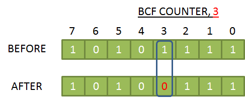
BCF FR, B
BCF clears the bit at location B in the FR register.
Example:
Let's say COUNTER=B'10101111', then BCF COUNTER, 3
makes COUNTER=B'10100111'. See figure below.
Note:
If the corresponding bit of FR is already zero, BCF does not alter anything.
AFFECTED FLAGS
BCF does not affect any flag.
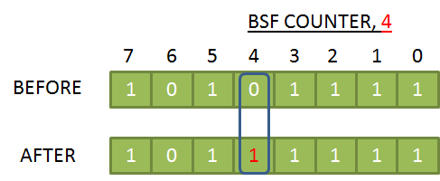
BSF FR, B
BSF sets (equates to 1) the bit at location B in the FR register.
Example:
Let's say COUNTER=B'10101111', then BCF COUNTER, 4
makes COUNTER=B'10111111'. See figure below.
Note:
If the corresponding bit of FR is already 1, BSF does not alter anything.
AFFECTED FLAGS
BSF does not affect any flag.
RRF FR, D
RRF rotates FR one bit to the right through Carry Bit and write the result to destination D.
The right most bit is moved to Carry Flag, C (Bit 2 of status register). Carry flag is moved to the left most bit location of FR.
The intermediate bits are shifted to the right.
Example:
Let's say COUNTER=B'10101111' and C=1, then RRF COUNTER, F
makes COUNTER=B'11010111' and C=1. See figure below.
AFFECTED FLAGS
RRF affects only C.
The least significant bit of FR is moved to C.
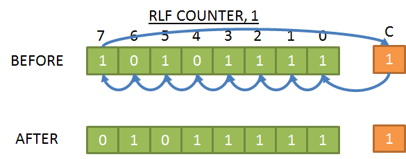
RLF FR, D
RLF rotates FR one bit to the left through Carry Bit and write the result to destination D.
The left most bit is moved to Carry Flag, C (Bit 2 of status register). Carry flag is moved to the right most bit location of FR.
The intermediate bits are shifted to the left.
Example:
Let's say COUNTER=B'10101111' and C=1, then RLF COUNTER, F
makes COUNTER=B'01011111' and C=1. See figure below.
AFFECTED FLAGS
RLF affects only C.
The most significant bit of FR is moved to C.
CLRW
CLRW clears W and sets Zero Flag.
AFFECTED FLAGS
CLRW affects only Z.
After CLRW, Z becomes 1.
CLRF FR
CLRF clears the content of FR and sets Zero Flag.
Example:
Whatever the previous value is, CLRF COUNTER
makes COUNTER=0.
AFFECTED FLAGS
CLRF affects only Z.
After CLRF, Z becomes 1.
NOP
NOP does nothing. It is generally used for generating delay.
AFFECTED FLAGS
NOP does not affect any flag.
BTFSC FR, B
BTFSC checks if bit B of register FR is equal to 0 or not. If it is NOT zero, program continues with the next line of code, otherwise skips next line.
BTFSC does not change the bit value, just checks. Bit B represents the location of the bit in the register. For the least significant bit, B is 0.
For most significant bit, B is 7.
Not always but frequently BTFSC is used to check the status of (Z, C and DC) flags (e.g BTFSC STATUS, 2 is used to check Z flag).
Example:
Let's say COUNTER=B'10101111'. In the following code BTFSC COUNTER, 3 GOTO LOOP1 GOTO LOOP2
, because the 3rd bit of COUNTER is 1, program makes a jump to LOOP1.
Example:
Let's say again COUNTER=B'10101111'. BTFSC COUNTER, 4 GOTO LOOP1 GOTO LOOP2
Now, the 4th bit is checked and it is 1, then program makes a jump to LOOP2.
AFFECTED FLAGS
BTFSC does not affect any flag.
BTFSS FR, B
BTFSS checks if bit B of register FR is equal to 0 or not. If it is zero, program continues with the next line of code, otherwise skips next line.
BTFSS does not change the bit value, just checks. Bit B represents the location of the bit in the register. For the least significant bit, B is 0.
For most significant bit, B is 7.
Not always but frequently BTFSS is used to check the status of (Z, C and DC) flags (e.g BTFSS STATUS, 2 is used to check Z flag).
Example:
Let's say COUNTER=B'10101111'. In the following code BTFSS COUNTER, 3 GOTO LOOP1 GOTO LOOP2
, because the 3rd bit of COUNTER is 1, program makes a jump to LOOP2.
Example:
Let's say again COUNTER=B'10101111'. BTFSS COUNTER, 4 GOTO LOOP1 GOTO LOOP2
Now, the 4th bit is checked and it is 0, then program makes a jump to LOOP1.
AFFECTED FLAGS
BTFSS does not affect any flag.
SWAPF FR, D
SWAPF interchanges the lower and higher nibbles of FR and writes the result to D. The higher nibble of a byte is
corresponding to the most significant four bits, and lower nibble is the remaining part (the least significant 4 bits).
For example higher nibble of B'1100 1111' is 1100 and the lower nibble is 1100. In hexadecimal format, it is easy to
see higher and lower nibbles directly. For example, higher nibble of 0XAB is A, lower nibble is B.
Example:
Let's say COUNTER=B'00001111', then SWAPF COUNTER, 1
makes COUNTER=B'11110000'. See figure below.
AFFECTED FLAGS
SWAPF does not affect any flag.
GOTO LABEL
GOTO makes a jumps to the code just under LABEL.
Example:
In the following program, LOOP1, LOOP2 and LOOP3 are representing labels. When the program is on line 2,
it makes a jump to line 6, and then line to 4, and then finally returns back to line 2. This process continues infinitely many times. 1 LOOP1 2 GOTO LOOP3 3 LOOP2 4 GOTO LOOP1 5 LOOP3 6 GOTO LOOP2
AFFECTED FLAGS
GOTO does not affect any flag.
SLEEP
After SLEEP instruction microcontroller goes into Standby Mode. SLEEP mode offers a very low current power-down
mode. The user can wake-up from SLEEP through
external RESET,
Watchdog Timer Time-out or
an interrupt.
.
AFFECTED FLAGS
TO becomes 1 and PD becomes 0 after SLEEP.
CLRWDT
CLRWDT clears Watch Dog Timer.
AFFECTED FLAGS
TO and PD becomes 1 after CLRWDT.
CALL LABEL
Calls the subroutine represented by LABEL.
AFFECTED FLAGS
CALL does not affect any flag.
RETURN
Returns from the routine CALLed.
AFFECTED FLAGS
RETURN does not affect any flag.
RETFIE
Returns from the interupt routine.
AFFECTED FLAGS
RETFIE does not affect any flag.
RETLW N
Returns from the routine. W becomes equal to N after this instruction.