Welcome. Online PIC compiler is a browser-based assembly compiler and simulator for PIC microcontrollers.
You can compile your assembly codes, download generated machine codes, debug and simulate the results online.
The following figure is a screenshot from the main page.
1) WORKSPACE:You write your assembly codes here. 2) COMPILE BUTTON: You can test your code for errors and compile it by clicking on this button. 3) CONSOLE:The errors and warnings appear here. 4) DEBUG AND SIMULATE BUTTON: After you compile your code if there is no error then you can test your code
via debugger/simulator tool. 5) CONFIGURATION MENU:You can change configurations codes such as code protection here. 6) MENU:
The location represented by number 6, is the menu from which you can
DO FILE OPERATIONS
Upload an "*.asm" file from your computer (Open/Save→Open .asm file)
To open a local file from your computer, just click on 'Open .asm file'
Download the codes that you write as an "*.asm" file (Open/Save→Save as .asm)
To download the codes on the workspace to your computer first write the a file name (without extension) then click on 'Save as .asm'
Download the generated machine code provided that your program compiled correctly (Open/Save→Save machine code)
To download generated machine codes, write the a file name (without extension) to the same space and then click on 'Save machine code'
The link becomes active only when compiling is accomplished without any errors.
SELECT A MICROCONTROLLER
Select 16F84A (Microcontroller→16F84A)
Currently only 16F84A link is active, for the other microcontrollers the compiler/debugger will be ready soon.
USE TOOLS
Use Base Conversion Tool (Tools→Base Conversion Tool)
Base Conversion tool is used to make conversions among binary, decimal and hexadecimal numbering systems. Just write a number to any one of the spaces
and click convert button to see its equivalent in other bases
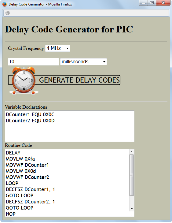
Use Delay Code Generator (Tools→Delay Code Generator)
Delay Code Generator can be used to generate delay routine codes, automatically. Just select the crystal frequency and enter the amount of delay that you want.
This tool will generate the codes you need in your programs.
USE QUICK HELP PAGES
Help (Help→Help)
From this pop-up you can reach basic, intermediate and advanced level
information about PIC programming as well as general information about Online PIC Compiler.
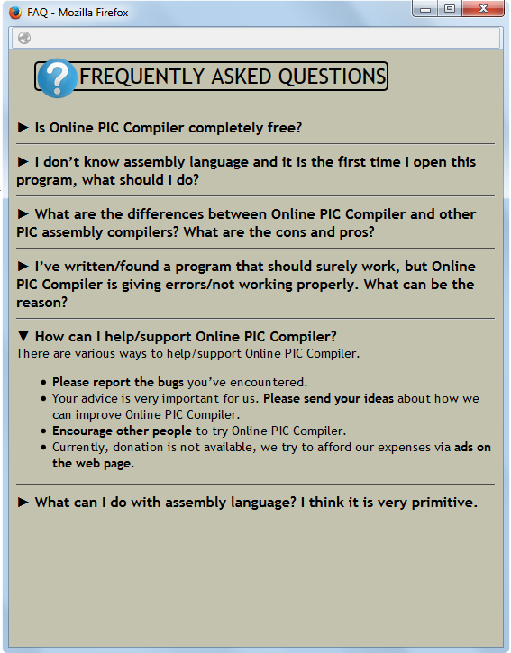
Frequently Asked Quesions (Help→FAQ)
Frequently asked questions and their answers can be found here.
Instructions and their descriptions (Help→Instructions)
The instruction set for 8-bit PIC microcontrollers can be found here.
As well as the summary and brief descriptions,
you can find detailed explanations and examples in this link
Datasheet (Help→Datasheet)
You can directly reach datasheet of the microcontroller via this link.
Pinout and descriptions (Help→Pinout)
You can find the Pinout and the description for each pin.
Memory Organization (Help→Memory Organization)
You can reach address for each register and the organization of RAM in this link.
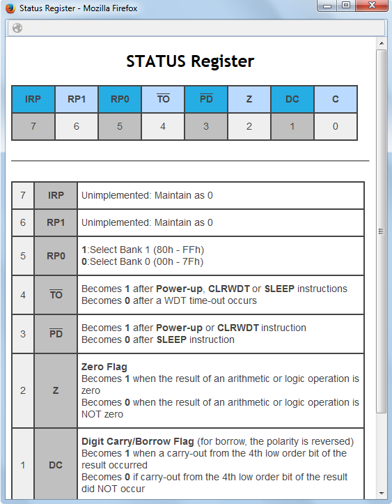
Status Register (Help→Status Register)
Each bit of status register is defined and described here.
Option Register (Help→Option Register)
Each bit of option register is defined and described here.
Intcon Register (Help→Intcon Register)
Each bit of intcon register is defined and described here.
ABOUT
GEMS SOFTWARE&ELECTRONICS
Online PIC compiler is developed by software developers and engineers of GEMS Software&Electronics.
Developers are
Dr. H. Emre KANKAYA,
Günsu KÖKSAL and
H. Erdinç KANKAYA.
We also appreciate the contributions of our trainees during the development process:
Hamidu Mbonde, Buğra Sertçelik, Yunus Emre Gazioğlu, Nurullah Mısır, Mehmet Ali İyikülah.
Your First Stand-Alone Application
It is quite easy and cheap to have a stand-alone application using PIC microcontrollers. For the first application, we just need
One 4MHz Cyrstal,
Two 22pF parallel plate capacitors,
One 220 Ohms resistor,
One LED (Color is optional),
One Normally Open (NO) Button (OPTIONAL- for resetting circuit),
One 10 kOhms resistor (OPTIONAL-for resetting circuit),
A PIC16F84A microcontroller and
A 5V supply
Just follow the steps below to have a flashing LED controlled by PIC16F84A
Click on Examples→LED Blink. The program codes will appear on the work space.
Click on Compile.
Download .hex file from Open/Save→ Save Machine Code. You should enter a name for the .hex file first.
Burn the .hex file to PIC16F84A. Plug out the microcontroller from the programmer.
Construct the circuit above. (If you do not want a resetting button in your circuit, connect MCLR pin directly to 5V supply)
Enjoy your first embedded application :)
Number Systems
There are infinitely many numbering systems in Mathematics, but three of them are essential for us: decimal,
binary and hexadecimal. You can use Base Conversion Tool to make conversions among those systems.
The following table illustrates the list of digits being used for each base.
Base
Digit
Binary (Base-2)
0, 1
Decimal (Base-10)
0, 1, 2, 3, 4, 5, 6, 7, 8, 9
Hexadecimal (Base-16)
0, 1, 2, 3, 4, 5, 6, 7, 8, 9, A, B, C, D, E, F
Generally speaking, for base-N, the digits 0 to N-1 are being used.
In hexadecimal format (base-16) the letters A to F represent numbers 10 to 15.
ALPHABET
NUMBER
A
10
B
11
C
12
D
13
E
14
F
15
Because microcontrollers are binary thinking devices, (logic or arithmetic) all operations are handled and all data chunks are in binary. However, it is not easy to manage them for us.
Hexadecimal number system is more compact and easier to handle in comparison with binary. Since the conversions between binary and decimal is not as straightforward as binary-hexadecimal conversions,
hexadecimal representation is more common in microcontroller programming.
Binary-to-hexadecimal conversion
Binary-to-hexadecimal conversion algorithm is quite easy to implement.
First, append zeros to the left hand side of the binary number unless the number of bits (digits) is divisible by four. (e.g 110010→00110010)
Then, cluster those bits in groups of four.(e.g 00110010→0011 0010)
Use the following table to represent each cluster in hexadecimal.(e.g 0011→3, 0010→2)
To convert a hexadecimal number to binary, just reverse the algortihm for binary-to-hexadecimal conversion. Find the binary representation of each digit, and them concatenate them. That's all!
For example, 0XAB has two digits: A and B. 1010 and 1011 are the equivalent binary representations according to the table above.
Then 0XAB is equal to 10101011, in binary.
Numbering Representations in Online PIC Compiler
There are 5 types of number representations in Online PIC compiler. Three of them are used to represent Hexadecimal numbers,
one is used for binary and the final one is used for decimal numbers.
A DECIMAL number starts with a letter D or d and the number is written between single quotes.
For example, to represent decimal 23, we write D'23'.
A BINARY number starts with a letter B or b and the number is written between single quotes.
For example to represent the binary number 110 we write B'110'.
There are three choices for hexadecimal numbers:
Similiar to previous representaions to represent hexadecimal number 7A either we use H'7A',
or 0X7A,
or 7A.
A bare number is always interpreted as a hexadecimal one.
Example:
All the following instructions set W to 100 (in decimal) MOVLW D'100' MOVLW 0x64 MOVLW H'64' MOVLW 64 MOVLW B'01100100'
Variable/Address Declaration
In Assembly language, variable and address declarations are made by using EQU directive. The declaration has the following format: Variable_Name EQU Number Variable_Name is the name given to a variable. There are just two restrictions for the Variable_Name:
It SHOULD NOT include single quote (').
It SHOULD NOT be in a numbering format(e.g. you can not use 0x64 as a variable name).
Any string obeying those rules is a valid Variable_Name. Number is the value or address assigned to the variable. It has to be in accordance with one of the numbering representation formats.
After the declaration of a variable, it can either be used as an address or a literal (constant number).
If the Variable_Name is used with an instruction ending with LW (such as ADDLW, MOVLW and etc.), it is interpreted as a literal.
However if it is used next to an instruction ending with F(such as ADDWF, MOVF, IORWF and etc.), it is interpretted as the address of a memory location in RAM.
Example:
Let's say the number 0XFF is stored in the address 0x15. After the declaration COUNTER EQU 0X15
the instruction MOVLW COUNTER
equates W to 0X15. However, after the instruction MOVF COUNTER, 0
W becomes 0XFF.
It is possible to declare two different Variable_Names into the same Number
e.g COUNTER1 EQU 0X15 COUNTER2 EQU 0X15
If you assign the same Variable_Name into two different numbers, the latter one will be valid.
e.g COUNTER1 EQU 0X15 COUNTER1 EQU 0X16
makes COUNTER1=0x16.
Labels
Label is a symbolic name for a specific line in your code.
Each location in the program memory is defined as a program word.
Each program word stores only one line of code (only the lines with instructions) in the program. For each program word an address is allocated, automatically, starting from 0.
Therefore, it means every line of code in the program has a corresponding address value.
Because it is not easy to count the number of instructions and calculate the address of each code,
to represent an address in the program memory (or a specific line) we use labels.
If a jump is required from one line to another through the program flow, first write a valid label
(a text without space or single quote) to the location to be jumped and then use GOTO instruction.
Labels are also used to start subroutines. CALL instruction is used to make a jump to a subroutine from any location in the program.
Each label is referencing to the next line in the program.
Example:
In the following program, the first line START is a label referencing to the line BSF PORTB, 0. Line 4 is used to make a jump to the code labelled by START.
So, after the execution of GOTO START program returns back to line 2, and continues. Whenever it reaches line 4, the program makes a jump to line 2. 1 START 2 BSF PORTB, 0 3 BCF PORTB,0 4 GOTO START
Labeling Rules
A label can not be a valid number representation. For example, you can not define 0X0F as a label.
A label should NOT include single quote.
Registers
Register is a memory space in the RAM. For 8-bit microcontrollers (e.g. 16F84A) each memory space is 8-bit (or 1
byte) long. There are two groups of registers in RAM: SFR (Special Function Registers) and GPR (General Purpose
Registers).
SFR are used for controlling peripheral functions of the microcontroller. They have permanent addresses in RAM.
For example PORTB register is always at location 0X06 for 16F84A and the programmer can not change this
location. Setting ports as input or output, enabling comparator units, running internal oscillator are all achieved
by setting and clearing appropriate bits in SFR. All settings of microcontrollers are hold in SFR.
TMR0, PCL, STATUS, FSR, PORTA, PORTB, EEDATA, EEADR, PCLATH, INTCON, OPTION_REG, TRISA, TRISB, EECON1
and EECON2 are available SFR in 16F84A.
Unlike SFR, GPR are free of use. They are designed to be used in the program flow. For example, if you want to
declare a counter to hold the number of increments in your program, a memory location among GPR has to be
allocated first. You can define names to the registers in GPR, store, manipulate, overwrite, read and erase
data whenever you want in your program flow. GPR have an address space 0X0C to 0X4F for 16F84A. Any address you declare out of this space is not valid.
W Register
W Register is an 8-bit hardware unit used to perform temporary operations during your program runs.
W Register is not located in RAM, that is why it does not have a defined address like SFR (Special Function Registers) (e.g. STATUS, PORTB).
W register can be used to transfer data from one GPR (General Purpose Registers) to another.
Let's say we have two registers NUM1 and NUM2 defined by EQU directive and we want to copy the content of NUM1 into NUM2.
Because there is no direct way of doing that, first we have to copy NUM1 to W using "MOVF NUM1, 0".
And, then, we have copy W to NUM2 using "MOVWF NUM2". Similar to data transfer, so as to perform arithmetic and logic operations over GPR, we again use W register.
Banks
In 16F family PIC microcontrollers, there is a bank structure in the memory. In the Memory Organization we see two colomns.
On this figure, each colomn is representing one bank. The one on the left is named as BANK 0 and the one on the right hand side is BANK 1. Some registers
(such as STATUS) appear
on both banks. Whichever the current bank is, the program can reach these registers.
But for the others (which appear only on one of the banks) to execute an operation (read, write or modify) the program has to be in the correct bank at that time.
An error occurs if you try to use a register while your microcontroller is not in the correct bank.
For example, to set PORTB pins as output, we have to clear TRISB, however while during that, the microcontroller has to be switched to BANK1.
Similarly in order to set or clear PORTB pins, because PORTB is in BANKS 0, microcontroller has to be in BANK 0.
There are two ways to select a bank.
The first method is accomplished by setting or clearing the 5.th bit of
STATUS register. Whatever the current bank is, if we write BSF, STATUS, 5
until the program reaches another code for bank selection, the bank being used becomes 1. Similarly, BCF, STATUS, 5
switches the bank to BANK 0.
The second way is to use BANKSEL instruction. If we use BANKSEL with a register name which only appears in BANK 0, microcontroller memory switches
to BANK 0 (e.g BANKSEL PORTB). Similarly, BANKSEL with a register which is only apparent in BANK 1 (e.g. BANKSEL TRISA) moves the memory to BANK 1.
Destination
Destination is used as the second parameter for instructions: ADDWF,
ANDWF,
COMF,
DECF,
DECFSZ,
INCF,
INCFSZ,
IORWF,
MOVF,
RLF,
RRF,
SUBWF,
SWAPF,
XORWF.
There are two options for the destination parameter: 0 or 1. Online PIC Compiler identifies W and w as 0; and F and f as 1.
But, you can even use 0 or 1, directly.
For the instructions listed above, if the destination is 0 (or w or W), the result of the operation is written to W.
If the destination is 1 (or f or F) the result is written into the register which is used as the other parameter in the instruction.
Example:
Let's say W=15 and COUNTER=63, then ADDWF COUNTER, F
makes COUNTER=78. W remains the same. If the destination is W (or 0), W becomes 78 and COUNTER remains the same.
Ports
I/O (Input/Output) Ports are hardware interfaces between microcontrollers and environment units. Data transmission in a port
is two-way, meaning that, both data gathering from a sensor and activating a motor driver are accomplished by the ports.
A port can not send and receive information at the same time. If you want to send a signal (such as a square wave) to a servo motor, you
have to set the port as "output". However, if you want to check whether a button is pressed or not, the button-connected port has
to be set as "input". In its output state, there are two options: LOGIC HIGH (5V) and LOGIC LOW(0V). Therefore, in total we have three
states (Input, Output-High and Output-Low) for a port. That's why I/O ports are called TRISTATE.
In PIC16F84A, there are in total 13 I/O ports, which are grouped in two clusters as PORTA and PORTB. Five of these I/O ports constitute
PORTA and the remaining eight constitute PORTB. PORTA includes the I/O ports
RA0, RA1, RA2, RA3 and RA4.
PORTB consists of
RB0, RB1, RB2, RB3, RB4, RB5, RB6 and RB7.
It is possible to read and write to all the pins in a PORT cluster, using a single instruction. For example, if PORTB is set as output
MOVLW 0XAA MOVWF PORTB
writes hexadecimal 0XAA (equivalently, binary 1010 1010) to PORTB. In terms of individual I/O ports, after those two instructions
are executed, RB7, RB5, RB3 and RB1 become logic 1 and RB6, RB4, RB2 and RB0 become logic 0. RB0 is always equivalent to the least
significant bit (LSB) of PORTB and RB7 is the most significant bit (MSB) of PORTB.
It is even possible to set or clear a single I/O pin in a port, as well.
For example,
BSF PORTB, 3
sets (makes logic 1) RB3 and
BCF PORTA, 0
clears (makes logic 0) RA0.
For each port, there exists a special function register to change the direction of the I/O pins in a port cluster. TRISA and TRISB are
responsible for the direction (being input or output) of PORTA and PORTB, respectively. Each bit in a TRIS register is controling one I/O
pin direction. For instance, bit 0 in TRISA is determining the direction of RA0 and bit 5 in TRISB is responsible for RB5.
Setting a bit (equate to 1) in TRIS register sets the correspoing I/O pin as input and clearing sets it as output.
For example,
BCF TRISB, 4
sets RB3 as output and
BSF TRISA, 1
sets RA1 as input.
Just like PORT registers, we can access and assign values all bits in TRISA and TRISB at the same time.
MOVLW 0X0F MOVWF TRISB
instructions causes RB7, RB6, RB5 and RB4 to be output and the RB3, RB2, RB1 and RB0 to be input.
If we use ports in our code, we always have to keep in mind that PORTA and PORTB are in BANK0 and TRISA and TRISB are in BANK1.
It means whenever we want to write or read PORTB or PORTA, the microcontroller has to be in BANK0 and to work with TRISA and
TRISB it is required to be in BANK1. Swiching among banks can be achieved by setting or clearing the 5th bit of STATUS.
With
BCF STATUS, 5
instruction, we can switch to BANK0 and
BSF STATUS, 5
do the inverse, thus we can move to BANK1. The following bunch of codes, sets PORTA input and PORTB output, then copies the data in PORTB to PORTA.
BSF STATUS, 5; Switch to BANK1 CLRF TRISB;PORTB is output MOVLW 0XFF;W=0XFF MOVWF TRISA;PORTA is input BCF STATUS, 5;Switch to BANK0 MOVF PORTA, 0;W=PORTA MOVWF PORTB;PORTB=W
Constructing Loops in Assembly
Roughly, there are three type of loops in assembly programming:
infinite loops, finite loops and conditional loops.
Infinite Loops
Every assembly program somehow need a sort of (direct or indirect)
infinite loop inside the code. The idea is to keep the program
counter (PC) between the minimum and maximum addresses. Just like
other programming languages, the instructions are processed in a
top-down manner. The first instruction executed in every program is
the first line appearing in the program. After each execution, PC is incremented by 1 automatically, unless the
executed instruction manipulates PC (such as GOTO, CALL,
RETURN...). If PC reaches an address, which does not contain any
instruction written by the programmer, it continues its way until the
program memory overflow. An overflow in the program memory
leads PC to restart its process from address 0. That has an effect
similiar to (not the same) resetting the microcontroller.
Not to encounter such issues in our programs, we have to somehow
keep PC inside our program lines. Even when we write one pass
algorithm, at the end of our program, we have to add a loop to force
PC to get stuck in there.
For example,
INFLOOP GOTO INFLOOP
is such a trap for PC. Once PC reaches GOTO INFLOOP line, it always
remains at the same point.
The following codepart always checks PORTA and copies into PORTB.
LOOP MOVF PORTA, 0 MOVWF PORTB GOTO LOOP
Unlike the previous example PC does not stuck in a line, rather it
moves among the last three lines continuously.
The following codepart can be considered as an infinite loop, as well.
It can be desirable to repeat a process a (finite) number of times. For
example, let's say we want to repeat a bunch of codes 10 times. One easy way of constructing a loop which repeats itself 10 times, is to define a COUNTER
COUNTER EQU 0X0C
starting with an initial value 10.
MOVLW 0X0A MOVWF COUNTER
The initial value has to be assigned outside of the loop.
In the loop COUNTER has to be decremented by one and checked whether it hits zero or not.
LOOP ..... DECFSZ COUNTER, 1 GOTO LOOP
The line "DECFSZ COUNTER, 1" first decrements COUNTER by 1 and writes the new value to itself (COUNTER=COUNTER-1). If the new value of COUNTER is zero, it skips the next line (GOTO LOOP). Then the loop is completed.
If the result of decrementing is non-zero (meaning that the loop is not repeated 10 times yet), GOTO LOOP instruction is executed and the process is repeated one more time until the result is zero.
 1) WORKSPACE:You write your assembly codes here.